Reflectance maps acquisition with gradient illumination
Measurements of reflectance properties of surfaces is becoming more and more important for many applications such as video games, virtual reality and architectural rendering. These properties include the diffuse and specular albedos, the normal map (normal vector at each point of the surface) and the roughness map (how shiny the material is at each point. The rougher, the less shiny the surface appear). Fortunately for flat surfaces the process of measuring these reflectance maps is simple using gradient illumination [1]. The software I used to compute these maps is available on my github.
The first step is to take pictures of a sample (here a HTC phone), illuminated with 0th, 1st and 2nd order spherical gradients. These gradients are defined over a sphere, hence a sphere of lights (light stage) should be used to illuminate the sample. However for flat surfaces, it is possible to illuminate the sample with a LCD screen only as a spherical to latitude longitude transformation allows to map the gradient on a 2D surface (see figure below).

Figure : Gradients used to illuminate the sample. From left to right. Top row : 0th order gradient, 1st order +X, 1st Order -X, 1st Order +Y, Bottom row : 1st order -Y, 2nd Order X gradient, 2nd Order Y gradient.
To be able to separate the diffuse and specular components of the reflectance, it is necessary to take pictures of the sample with parallel and cross polarized illumination. This is done by using a polarizer on the camera and a LCD panel that emits linearly polarized light (which is quite common). The final set of pictures of the sample illuminated by the gradients in parallel and cross polarized light is shown in the following figures.

Figure : Phone illuminated by gradient illumination in parallel polarisation. From left to right : 0th order gradient, 1st order +X, 1st Order -X, 1st Order +Y, 1st order -Y, 2nd Order X gradient, 2nd Order Y gradient.
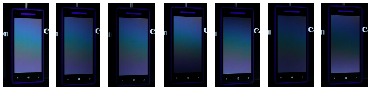
Figure : Phone illuminated by gradient illumination in cross polarisation. From left to right : 0th order gradient, 1st order +X, 1st Order -X, 1st Order +Y, 1st order -Y, 2nd Order X gradient, 2nd Order Y gradient. Note how the phone screen changes reacts to polarisation producing birefringent colours.
Then some surprisingly simple per-pixel operations between these images allow to recover the reflectance maps as explained by Ghosh et al. [1].

Figure : Reflectance maps. From left to right : diffuse albedo, specular albedo, normal map, roughness map.
![Figure : Rendering of the HTC phone using the reflectance maps. The diffraction on the phone's screen was rendered using Toisoul&Ghosh 2017 method [2].](https://images.squarespace-cdn.com/content/v1/5d7b6b83ace5390eff86b2ae/1568412080774-JWP6IX8RVHYO6PB0EB3I/phone_rendering.png)
Figure : Rendering of the HTC phone using the reflectance maps. The diffraction on the phone's screen was rendered using Toisoul&Ghosh 2017 method [2].
Note that it is also necessary to image a checkerchart for color balancing. More explanations on how to use the software are available on my github.
Such a technique does not work well on samples that affect polarization of light. For instance, it is the case of holographic papers. In this example, the phone’s screen changes polarization as shown by the dispersion of white light in the cross polarization measurements. As a result the diffuse-specular separation is discarded for the phone’s screen as it would give incorrect results (the screen is assumed to be only specular).
Finally the method can still be used for surfaces with a more complex geometry. However it requires very specialized equipment such as a light stage to illuminate the sample from an entire sphere of directions.
References
[1] Estimating Specular Roughness and Anisotropy from Second Order Spherical Gradient Illumination. Abhijeet Ghosh, Tongbo Chen, Pieter Peers, Cyrus A. Wilson, Paul Debevec. Computer Graphics Forum (Proc. EGSR), 28(4), June 2009, pp. 1161-1170.
[2] Practical Acquisition and Rendering of Diffraction Effects in Surface Reflectance. Antoine Toisoul and Abhijeet Ghosh. ACM Transactions on Graphics, 36(5), 2017.